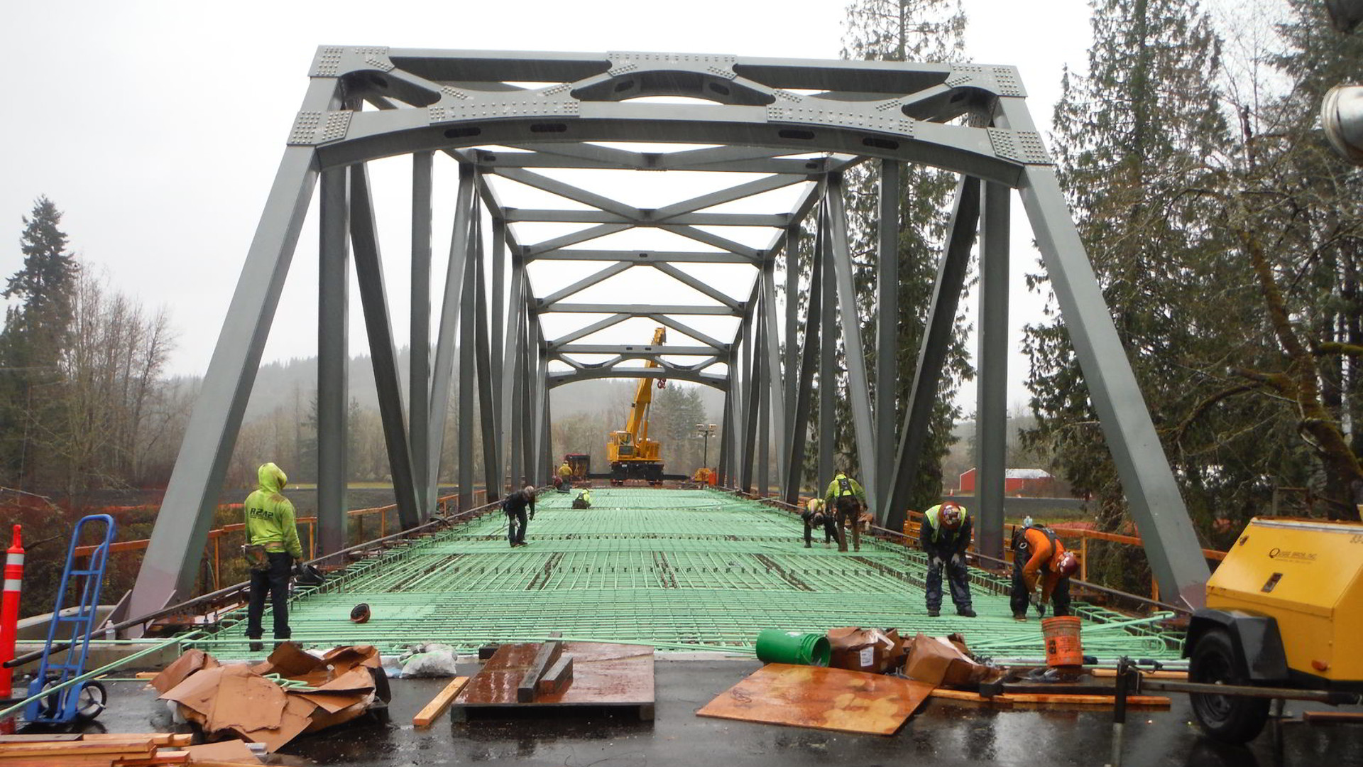
In addition to my building-related experience, I have worked on a number of new and existing bridge projects. 建築関連の経験に加えて、私は数多くの新規および既存の橋プロジェクトに携わってきました。
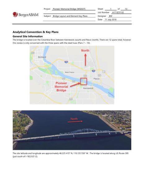
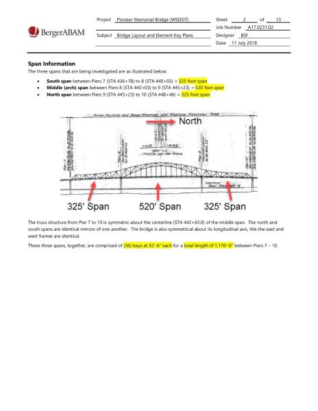
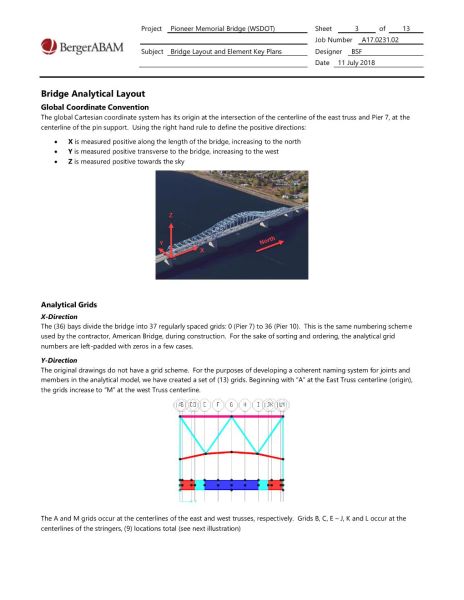
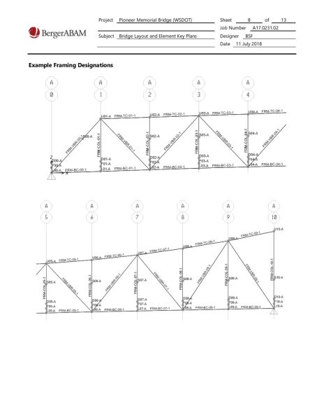
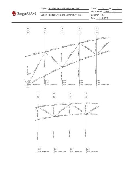
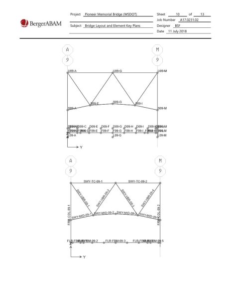
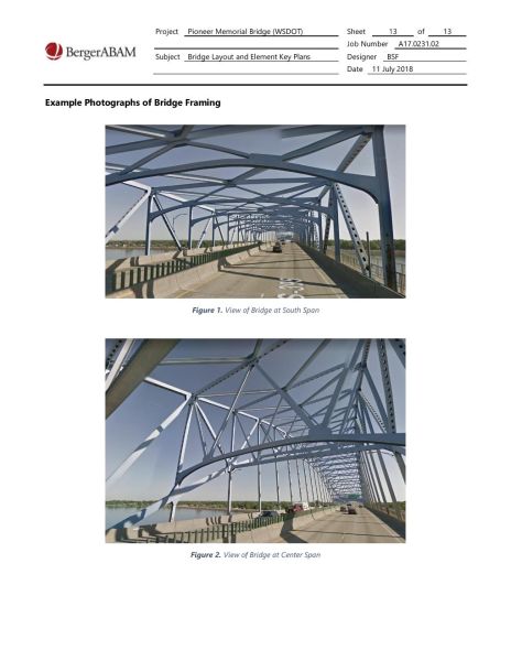
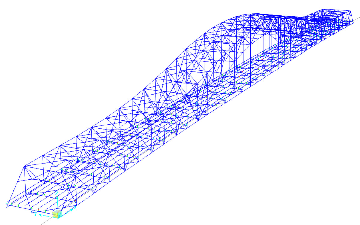
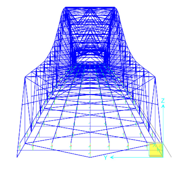
I have experience building and running FEA models using cutting edge analysis software such as CSi Bridge, SAP2000 and MIDAS. The following images are pages from an example narrative that I created to explain how I developed and created a multi-span bridge over the Columbia River in Washington State. I think it's important to do this to help others understand my modeling process, and to aid in post-processing the data from large, complex models. 私は、 CSi Bridge、SAP2000、MIDAS などの最先端の解析ソフトウェアを使用して FEA モデルを構築および実行した経験があります。次の画像は、ワシントン州のコロンビア川に架かる複数径間橋をどのように開発および作成したかを説明するために作成したサンプル ナラティブのページです。これを行うことは、他の人が私のモデリング プロセスを理解しやすくするため、また大規模で複雑なモデルからのデータの後処理を支援するために重要であると考えています。


I regularly build FEA models using FEA software, in concert with Excel, text files, and coding languages such as C#, VBA and VB.NET and Python. Using coding to ensure accuracy and consistency while reducing time and workload are critical in building complex models. 私は、Excel、テキスト ファイル、C#、VBA、VB.NET、Python などのコーディング言語と連携して、FEA ソフトウェアを使用して FEA モデルを定期的に構築しています。複雑なモデルを構築する場合、コーディングを使用して時間と作業負荷を削減しながら精度と一貫性を確保することが重要です。

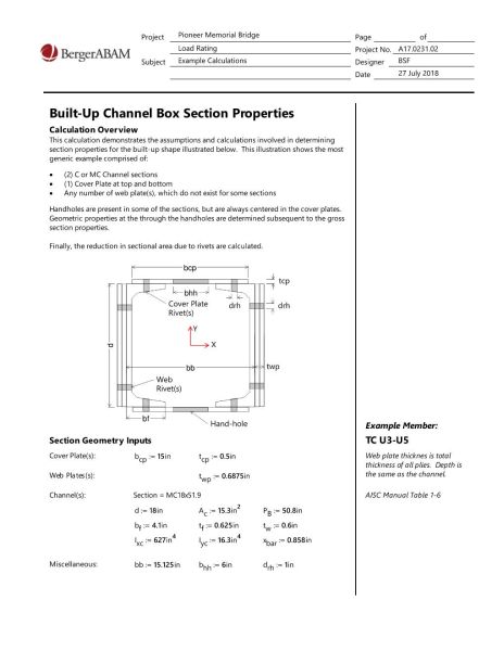
Example custom built-up member cross-sections used in modeling frame elements of the FEA model. I use the technology, but don't just trust it — I verify it by independent means. FEA モデルのフレーム要素のモデリングに使用されるカスタム構築部材の断面の例。私はそのテクノロジーを使用していますが、ただ信頼しているだけではなく、独立した手段でそれを検証しています。


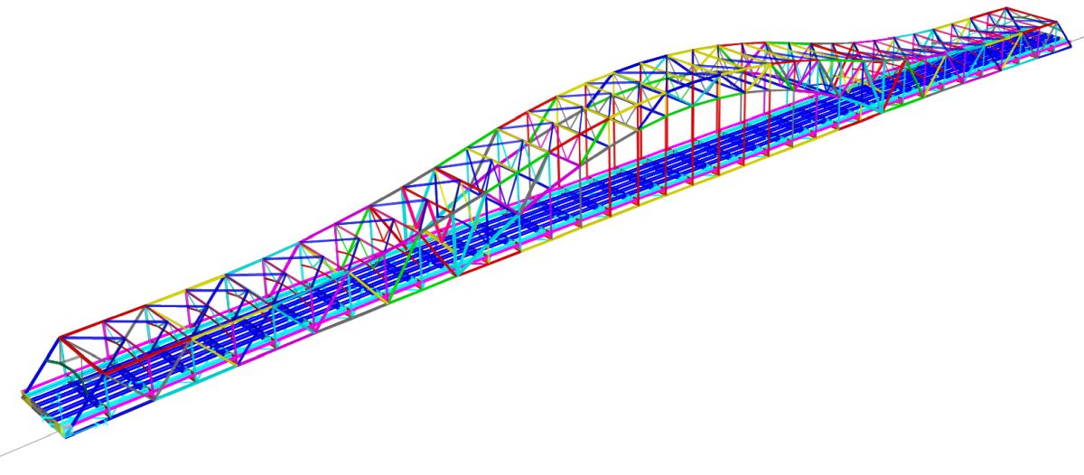
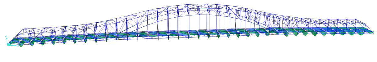
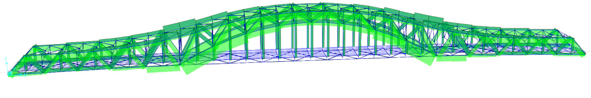
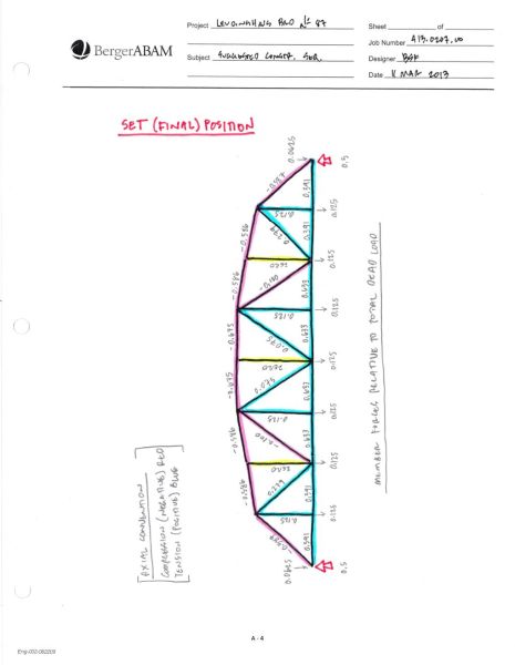
These images illustrate meaningful results of member axial forces and normalized limiting stresses, etc. Illustrations like these are helpful in verifying overall force flow and behavior of the model. これらの画像は、部材の軸力や正規化された限界応力などの意味のある結果を示しています。このような図は、モデルの全体的な力の流れと動作を検証するのに役立ちます。


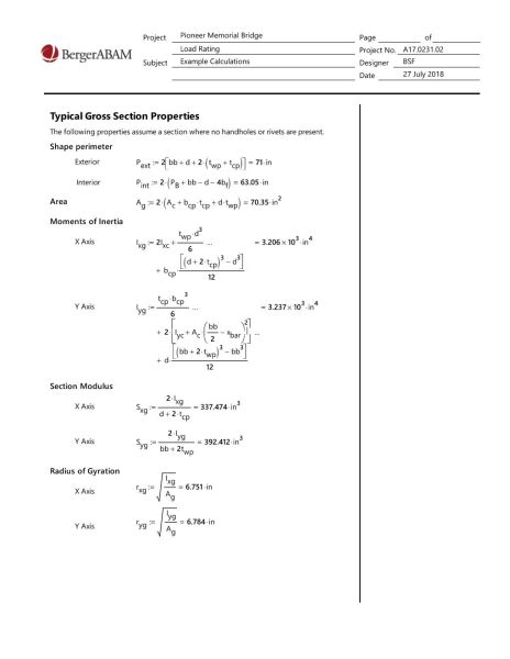
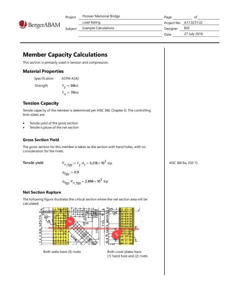
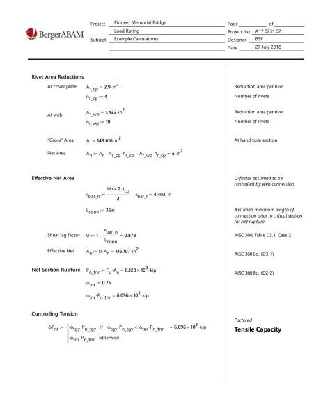
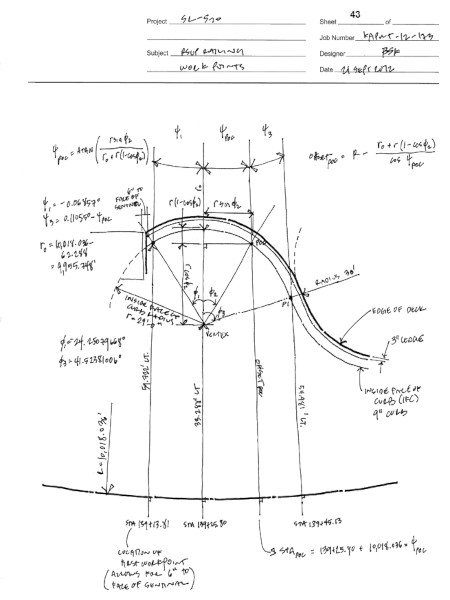
I often extract the analysis results and post-process the data outside the FEM software. This allows me to accomplish more tasks, faster and more accurately. The following pages are example calculations that demonstrate my post-processing workflow algorithms. 私は解析結果を抽出して、FEM ソフトウェアの外部でデータを後処理することがよくあります。これにより、より多くのタスクをより速く、より正確に実行できるようになります。次のページは、後処理ワークフロー アルゴリズムを示す計算例です。


On this and many similar projects, I used the following industry standards for my analysis and designs. Needless to say, I have extensive experience with these documents. このプロジェクトおよび多くの同様のプロジェクトでは、分析と設計に次の業界標準を使用しました。言うまでもなく、私にはこれらの文書に関する豊富な経験があります。

I have experience working on high-profile bridges, with large, fast-paced design-build joint-ventures and lots of public attention. I know how to work on tight-schedules, under pressure, with the stress and strain of involvement from highly invested stakeholders. 私には、大規模でペースが速い設計・建設の合弁事業があり、世間の注目を集めている、注目度の高い橋に携わった経験があります。私は、多大な投資を行っている関係者からの関与によるストレスと負担にさらされながら、厳しいスケジュールに取り組む方法を知っています。

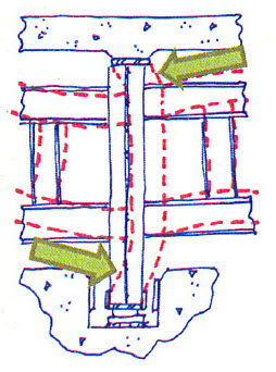
I designed the diaphragm systems at the 250-foot long steel transition spans of a major regional floating bridge. These diaphragms must resist extreme loading from several sources including large earthquakes. 私は、地域の主要浮橋の 250 フィートの長さの鋼製移行スパンでダイヤフラム システムを設計しました。これらのダイヤフラムは、大地震を含むいくつかの原因からの極度の負荷に耐える必要があります。
Plate diaphragms are typical used, but this client wanted to openings that allowed maintenance workers to pass through the diaphragms. I designed diaphragms based on the Vierendeel truss concent. 一般的にはプレートダイヤフラムが使用されますが、このクライアントはメンテナンス作業者がダイヤフラムを通過できる開口部を希望していました。フィーレンディールトラスコンセントに基づいて振動板を設計しました。
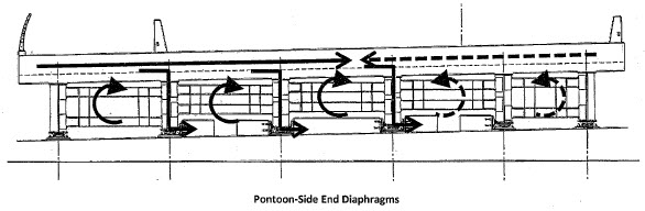
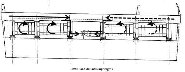
The Vierendeel truss concent allows for easy to install bolted connections at the bridge floor beam webs, with a shop-fabricated moment connection to provide the diaphragm shear stiffness. フィーレンディール トラス コンセントにより、ダイヤフラムのせん断剛性を提供するために工場で製造されたモーメント接続を使用して、橋の床の梁ウェブにボルト接続を簡単に取り付けることができます。
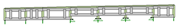
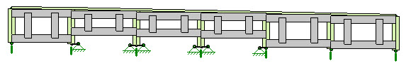
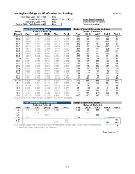
Example results summary showing the design demands in the diaphragm framing members. ダイヤフラムフレーム部材の設計要件を示す結果の概要の例。

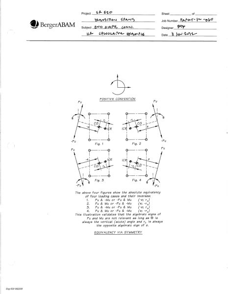
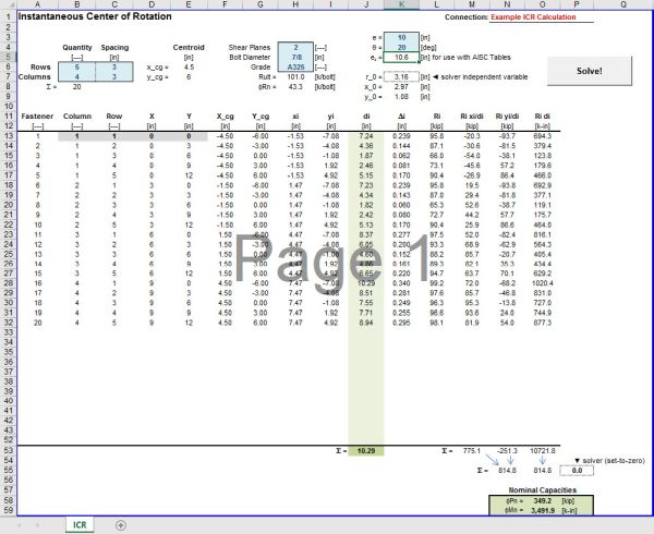
Based on my years of steel building experience, my design using the instantaneous center of rotation method I was able to make bolted connections feasible. This allowed the diaphragms to be shop fabricated and field installed - allowing faster construction and major savings. 長年の鉄骨建築の経験をもとに、瞬間回転中心法を用いた設計によりボルト締結を実現することができました。これにより、ダイアフラムを工場で製造して現場で設置できるようになり、より迅速な構築と大幅な節約が可能になりました。
This images show an ICR calculator that I created that performs the analysis and design of bolt groups based, which accepts batch demand inputs. この画像は、バッチ需要入力を受け入れるボルト グループ ベースの分析と設計を実行する、私が作成した ICR 計算機を示しています。

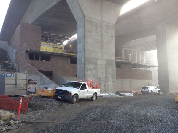
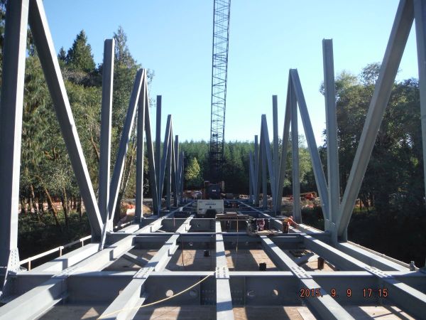
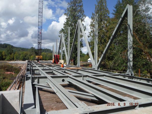
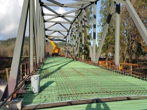
The following are pictures of the diaphragms as well as the construction process of the steel transition spans. 以下は、ダイヤフラムと鋼製移行スパンの建設プロセスの写真です。


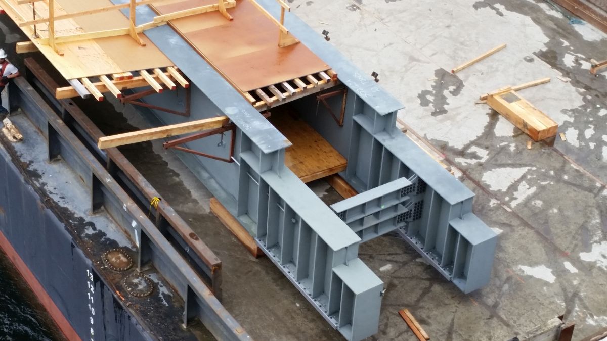
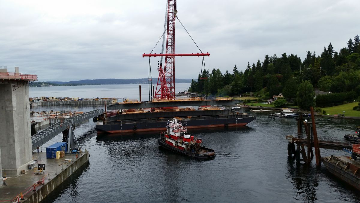
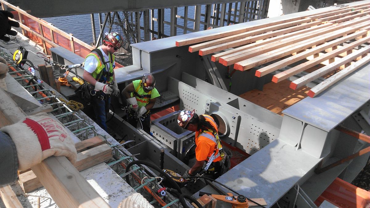
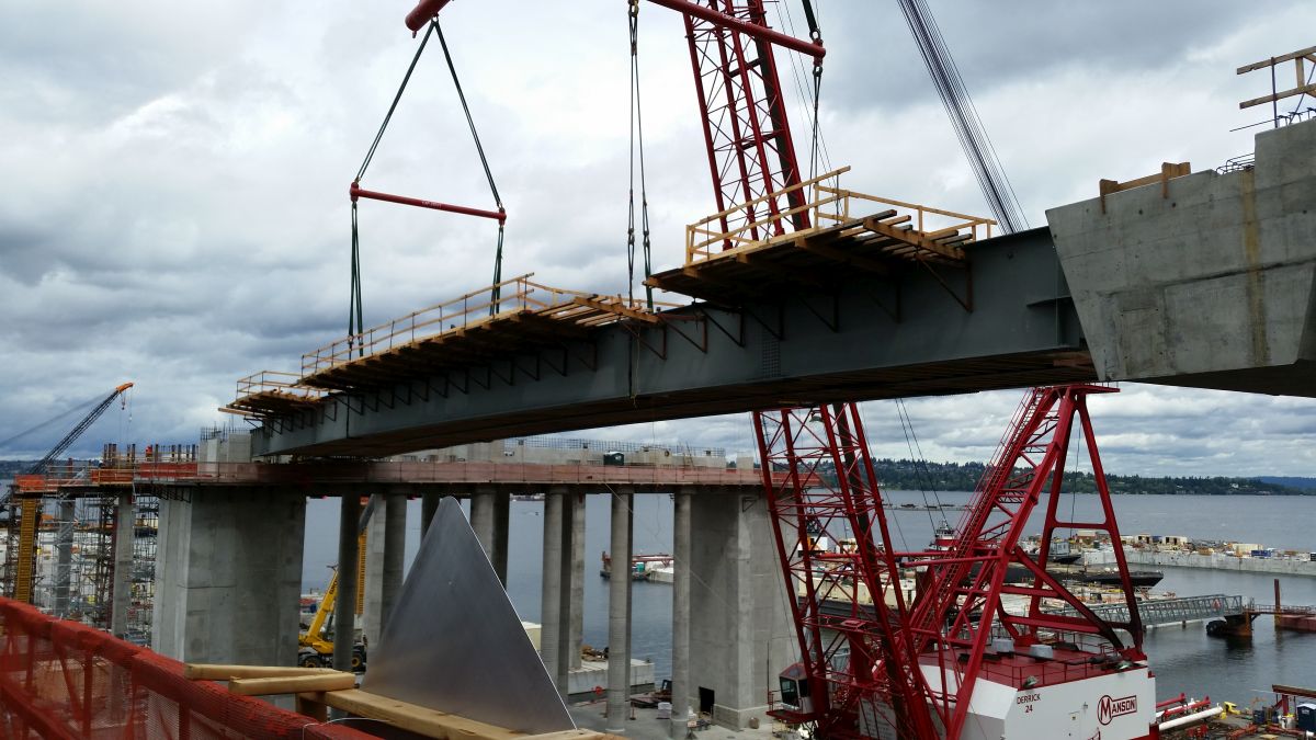
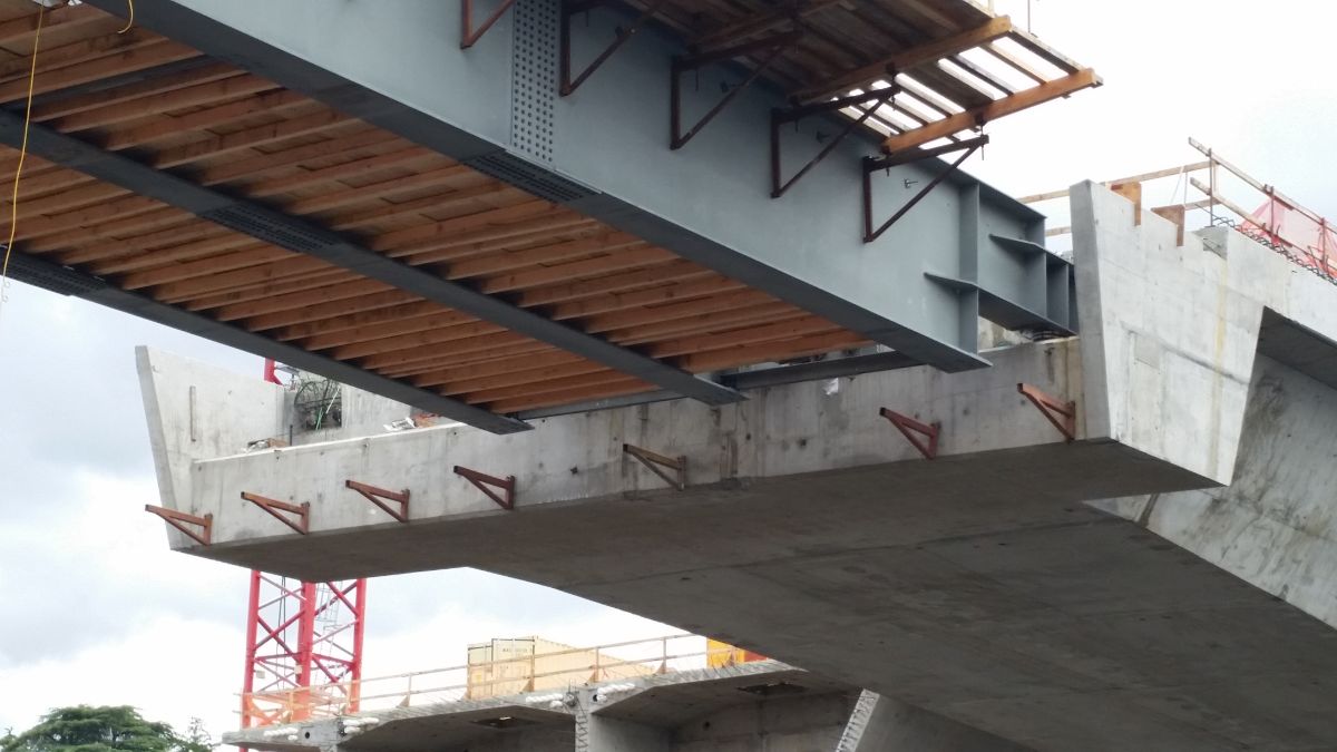
Gallery of images relating to the steel transition spans that I worked on. 私が取り組んだ鋼移行スパンに関連する画像のギャラリー。
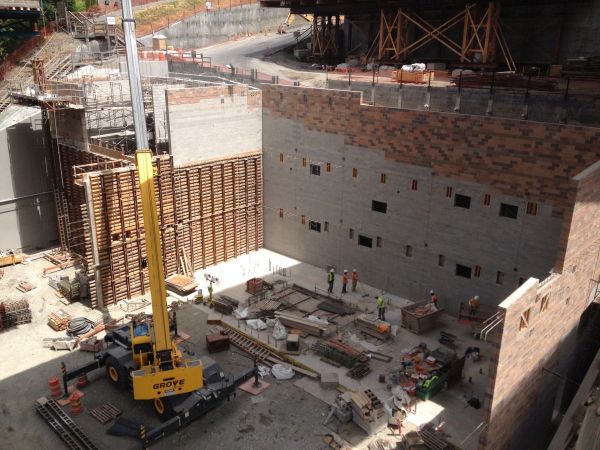
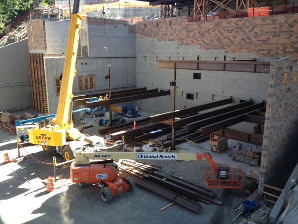
I also did the conceptual design of a three-story CMU administration building located under the east end of the bridge. I didn't end up finishing this building design as I was assigned to be a field engineer for another project I had worked on for several years. 橋の東端の下にある 3 階建ての CMU 管理棟の概念設計も行いました。私は数年間取り組んできた別のプロジェクトのフィールド エンジニアとして割り当てられたため、この建物の設計は最終的には完了しませんでした。

I have experience designing with aluminum using the Aluminum Design Manual on both buildings and bridges projects. For this project, I designed aluminum railing that lined two-miles worth of the floating bridge pedestrian and bicyclist path. This railing was not made from standard off-the-shelf shapes, but custom built custom cut and welded shapes. 私は、建物と橋のプロジェクトの両方で、アルミニウム設計マニュアル(ADM)を使用してアルミニウムを使用して設計した経験があります。このプロジェクトでは、浮橋の歩行者と自転車用通路の 2 マイル相当に沿って並ぶアルミニウムの手すりを設計しました。この手すりは、標準的な既製の形状から作られたのではなく、カスタムメイドのカスタムカットおよび溶接形状で作られました。
To deliver a design that allowed the sleek, elegant railing shapes I had to use 6000 temper and welded connections. Only certain aluminum tempers can be welded. I used SAP2000 to analyze the design stresses. In the end the rail panels need to be heat-treated and artificially aged to regain much of the strength lost through welding. 滑らかでエレガントな手すりの形状を実現するデザインを実現するには、6000回の焼き戻しと溶接接続を使用する必要がありました。特定の質のアルミニウムのみを溶接できます。SAP2000 を使用して設計応力を分析しました。最終的に、溶接によって失われた強度の多くを取り戻すために、レール パネルを熱処理し、人工的に老化させる必要があります。
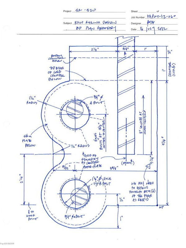

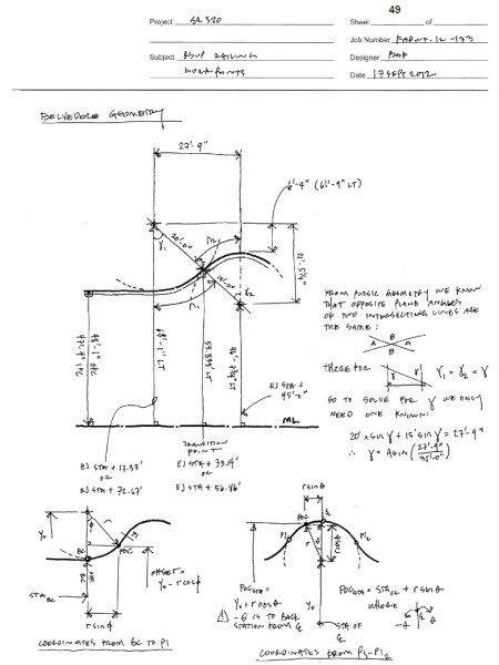
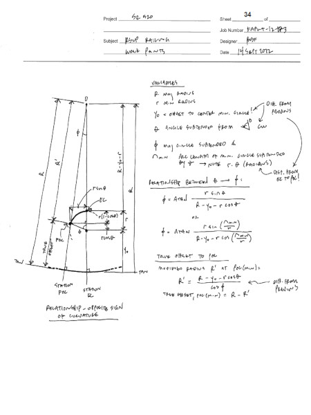
I also developed equations that helped the contractor to locate the base connection for thousands of panels for two-miles of railing. The railing path followed horizontal and vertical curves throughout. With my derivations, the contractor was able to install the railing with no reported rework. また、請負業者が 2 マイルの手すりにある数千枚のパネルのベース接続を見つけるのに役立つ方程式も開発しました。手すりの通路は全体に水平および垂直の曲線をたどっていました。私の推測によれば、請負業者は手戻りの報告もなく手すりを設置することができました。
Images of one of the aluminum railing panels delivered to the site, ready to be installed. 現場に搬入され、設置準備が整ったアルミ製手すりパネルの1枚。


I have experience with cranes, whether as part of the construction process, or as a permanent feature of the facility. 私には、建設プロセスの一部として、または施設の恒久的な機能として、クレーンに関する経験があります。
For this project I worked with several crane suppliers to determine different options for erecting a bridge over a river without putting any supports into the water. このプロジェクトでは、私はいくつかのクレーン サプライヤーと協力して、水中に支柱を入れずに川に橋を架けるためのさまざまなオプションを決定しました。
I developed several options for erecting the bridge, each of which needed to be analyzed using finite element analysis to determine the effects on the members and connections. 私は橋を建設するためのいくつかのオプションを開発しましたが、それぞれのオプションを有限要素解析を使用して解析して、部材と接続への影響を判断する必要がありました。


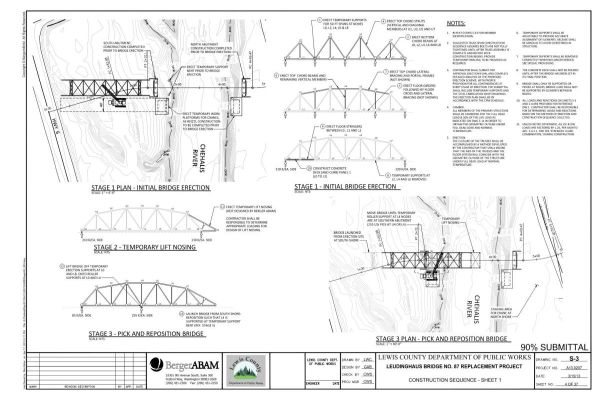
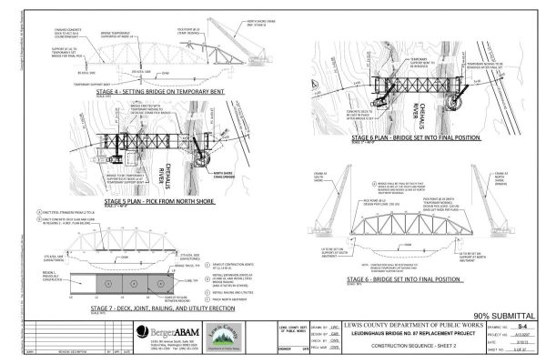
I developed drawings with specific instructions on the sequence for the concept selected by the client: install a temporary snout on the cantilevered end of the bridge and launch from one shore. A crane from the opposite shore will pick up the snot and safely support the cantilevered end until it rests on the far shore. 私は、クライアントが選択したコンセプトのシーケンスに関する具体的な指示を含む図面を作成しました。つまり、橋の片持ち梁の端に一時的なスナウトを設置し、一方の岸から発射します。対岸からクレーンが鼻水を拾い上げ、片持ち梁の端が対岸に着くまで安全に支えます。
I also served as the design QC manager for the project. I reviewed other engineer's calculations and analysis and provided comments the helped ensure code compliance and safe and economic designs. 私はこのプロジェクトの設計 QC マネージャーも務めました。私は他のエンジニアの計算と分析をレビューし、コードへの準拠と安全で経済的な設計の確保に役立つコメントを提供しました。

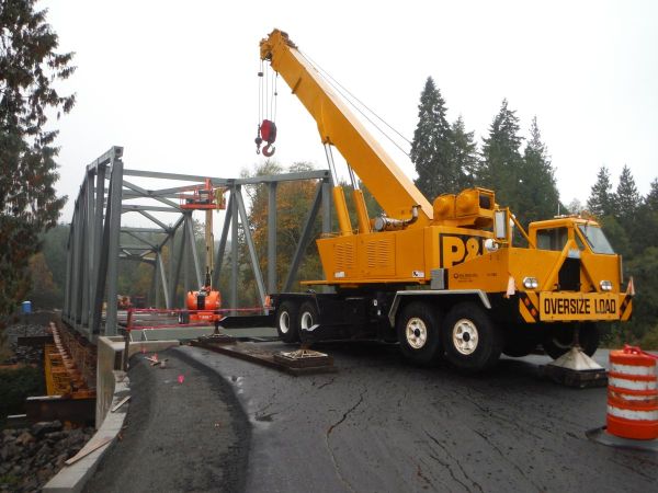
The following photos show several stages of the construction process. The cost data generated from my evaluation of the erection concepts helped stakeholders select a method that balanced cost and environmental impact concerns. 次の写真は、建設プロセスのいくつかの段階を示しています。私の建設コンセプトの評価から生成されたコスト データは、関係者がコストと環境への影響の懸念のバランスをとる方法を選択するのに役立ちました。


I have been involved in several bridge load rating projects. Typically my involvement has been with creating analytical models, or developing digital tools for post-processing analytical model results. 私はいくつかの橋梁評価荷重プロジェクトに携わってきました。通常、私は分析モデルの作成、または分析モデルの結果を後処理するためのデジタル ツールの開発に携わってきました。
I have used several different tools on the market, including CSi Bridge. Commercial available software does have its limits. I participated in a project for a state DOT that involved reviewing several existing concrete bridges with sloping, concrete arch support members. The software we had could not perform load ratings of these types of members. 私は CSi Bridge など、市販のさまざまなツールをいくつか使用してきました。市販のソフトウェアには限界があります。私は州運輸局のプロジェクトに参加しました。このプロジェクトでは、傾斜したコンクリート アーチの支持部材を備えたいくつかの既存のコンクリート橋を検討しました。私たちが使用していたソフトウェアでは、このようなタイプの部材の荷重評価を実行できませんでした。

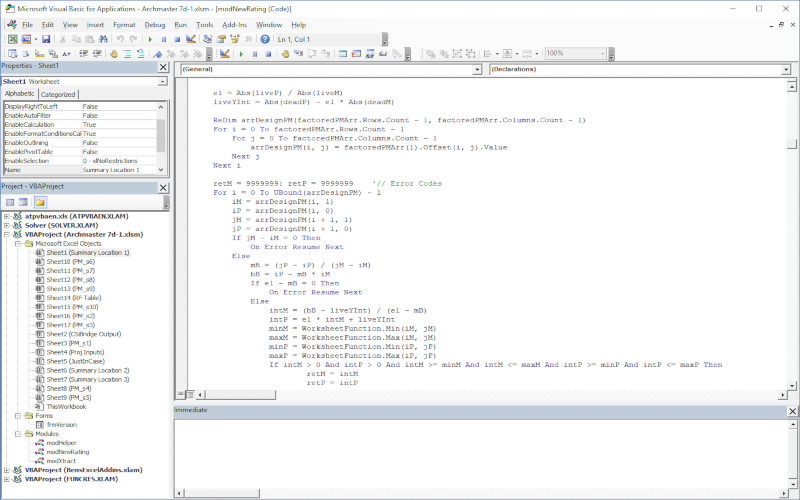
I developed software that consumed the member forces from CSi Bridge and performed extensive load rating calculations. Development of the code took several days, but saved several months of manpower time in analysis. 私は、CSi Bridge からメンバーの力を消費し、広範な定格荷重計算を実行するソフトウェアを開発しました。コードの開発には数日かかりましたが、分析にかかる人的時間を数か月節約できました。
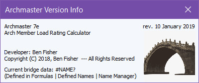
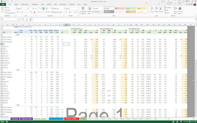
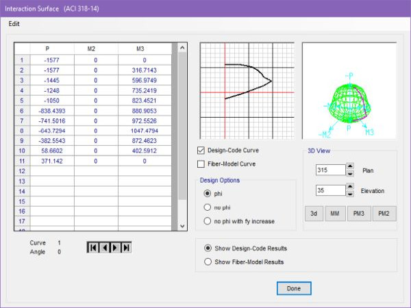
The following images show screenshots of my app. The code consumes geometric information about the members, develops PM diagrams, consumes batch load data and compares the demands to capacities, and reports individual load rating values. Thousands of locations and load cases can be calculated in milliseconds. 次の画像は、私のアプリのスクリーンショットを示しています。このコードは、メンバーに関する幾何学的情報を使用し、PM 図を作成し、バッチ負荷データを使用して需要と容量を比較し、個々の負荷定格値をレポートします。数千の位置と荷重ケースをミリ秒単位で計算できます。
This image illustrates one of the PM diagrams with nominal and design capacity envelopes, with the demands shown as red-Xs. My app provides these diagrams as a byproduct, which help the designer quickly verify complex results. この画像は、公称容量エンベロープと設計容量エンベロープを備えた PM ダイアグラムの 1 つを示しており、需要は赤い X で示されています。私のアプリは副産物としてこれらの図を提供し、設計者が複雑な結果を迅速に検証するのに役立ちます

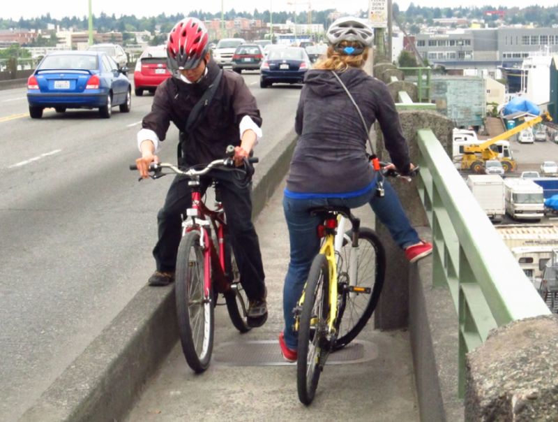
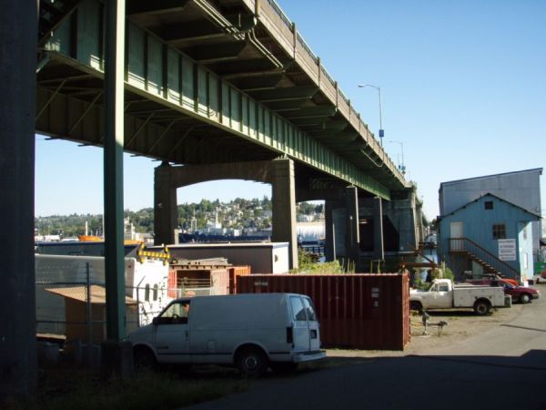
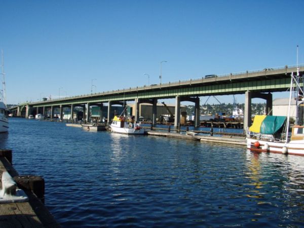
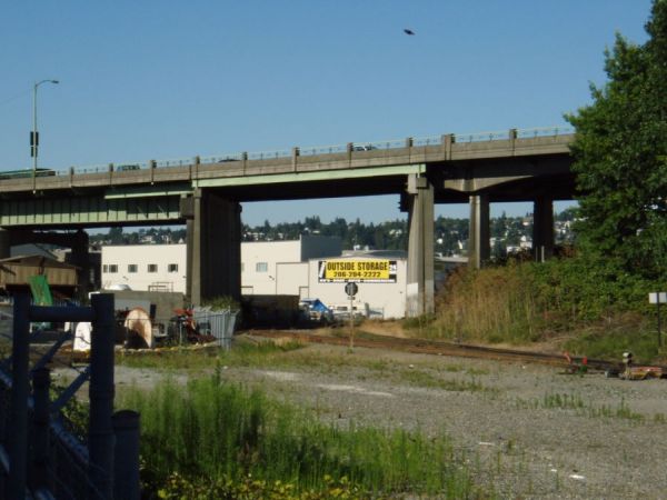
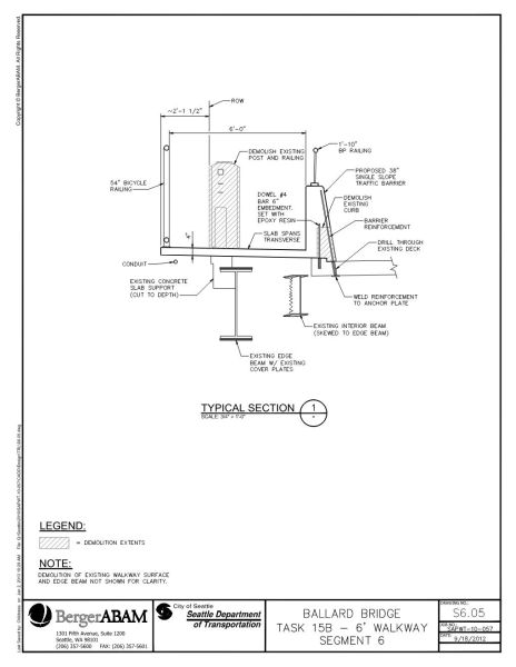
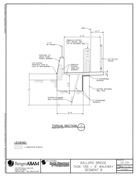
I have worked on a handful of bridge projects that focus on the needs of pedestrians. On the project shown here, I took measurements on location, developed drawings and designs for expanding service for pedestrians and cyclists on a heavily used bridge in Seattle. 私は歩行者のニーズに焦点を当てたいくつかの橋プロジェクトに取り組んできました。ここに示されているプロジェクトでは、シアトルの頻繁に使用されている橋で歩行者と自転車利用者へのサービスを拡大するために、現場で測定し、図面と設計を作成しました。
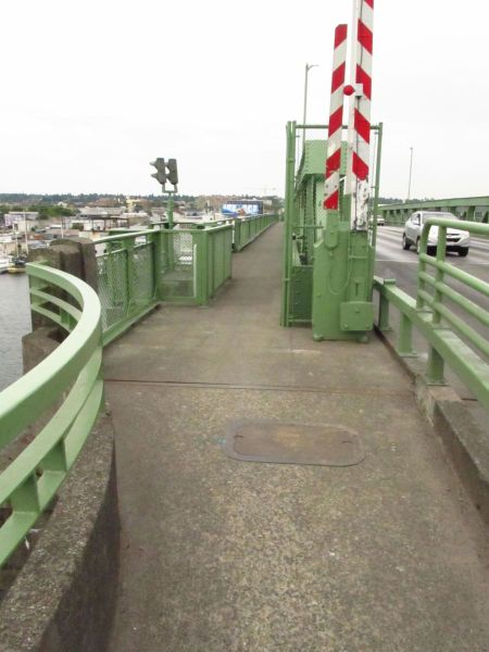
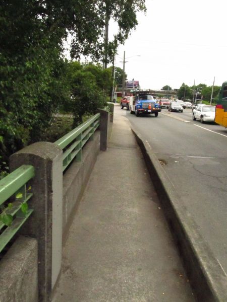
Prior to developing structural expansion concepts, I performed a site survey to collect measurements, verify the as-built data, and to determine if there were unrecorded concerns or issues. 構造拡張のコンセプトを策定する前に、現場調査を行って測定値を収集し、竣工データを検証し、記録されていない懸念や問題がないかどうかを判断しました。

Below are concept sketches of my expansion designs that considered several conditions along the length of the bridge. 以下は、橋の長さに沿ったいくつかの条件を考慮した私の拡張設計のコンセプト スケッチです。


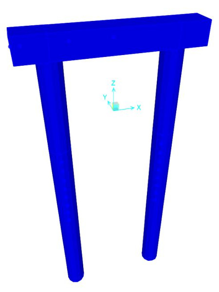
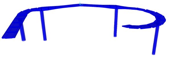
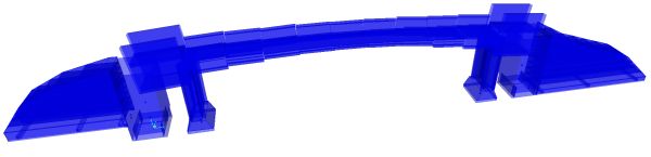
I have performed nonlinear static (pushover) and linear dynamic analyses on existing bridges. I used CSi Bridge to create finite element models of the concrete bents to study the fuse behavior. 既存の橋に対して非線形静的 (プッシュオーバー) 解析と線形動的解析を実行しました。CSi Bridge を使用してコンクリートの曲がりの有限要素モデルを作成し、ヒューズの動作を研究しました。
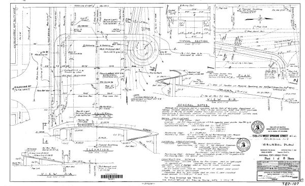
Examples of the existing drawings that I used to create analysis models from. 解析モデルの作成に使用した既存の図面の例。
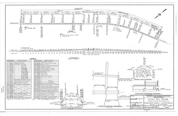

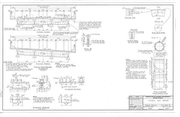

I enjoy the process of trying search for clues and piece together as-built information. It's like solving a puzzle or a mystery when it's finished. 私は手がかりを探して、完成した情報をつなぎ合わせるプロセスを楽しんでいます。完成するとパズルや謎を解くようなものです。
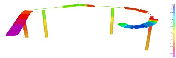
I used LPile to determine equivalent soil springs. I also developed a small applet that quickly formats LPile outputs as springs for CSi FEA software such as Bridge or SAP2000. LPileを使用して同等の土壌泉を決定しました。また、LPile 出力をBridgeやSAP2000などのCSi FEAソフトウェア用のスプリングとしてすばやくフォーマットする小さなアプレットも開発しました。
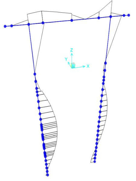
Based on my experience with building seismic design, I was able to quickly adapt to the AASHTO approach to nonlinear static analysis of lateral loads. The hinge parameters are slightly different, but the overall approach is similar. The images below show screenshots from my analysis. 建物の耐震設計の経験に基づいて、横荷重の非線形静的解析に対する AASHTO アプローチにすぐに適応することができました。ヒンジのパラメータは若干異なりますが、全体的なアプローチは似ています。下の画像は、私の分析のスクリーンショットを示しています。


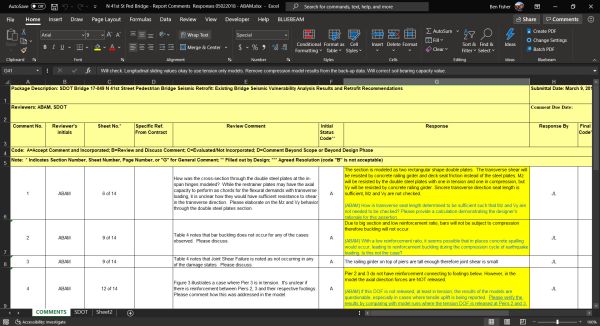
I have performed several third-party peer reviews on the work of structural engineers from other firms. My experience with advanced analysis, as well as design and construction experience helps me provide meaningful reviews. 私は、他の会社の構造エンジニアの仕事について、第三者によるピアレビューをいくつか行ってきました。高度な分析の経験と、設計と建設の経験が、有意義なレビューを提供するのに役立ちます。
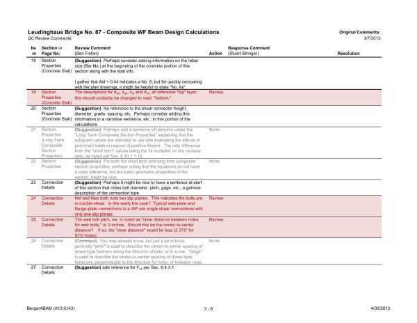
This image shows a spreadsheet of review comments I generated as part of my peer review work. この画像は、査読作業の一環として私が生成した査読コメントのスプレッドシートを示しています。
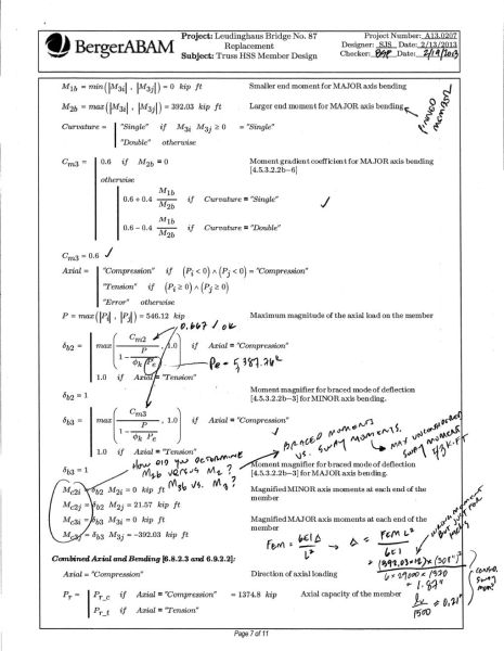
Sometimes my work as a peer review also includes the need to perform independent technical verifications. Sometimes these can me simple hand calcs (shown), and sometimes more detailed modeling investigations. ピアレビューとしての私の仕事には、独立した技術検証を実行する必要がある場合もあります。場合によっては、これらを単純な手作業で計算することもできます (図を参照)。また、場合によっては、より詳細なモデリング調査を行うこともできます。
